The edge trigger ribbon also serves choke functionality.
There is a similar 2 conductor ribbon for the bell.
The ribbon connection to the PCB connector often fails for one of two reasons that I have experienced:
1) The ribbon can become loose and not fully seated in the connector on the cymbal PCB
2) The ribbon can be kinked or bent so tightly that it causes a break in the ribbon circuit
Fixing either of these issues requires removing the rubber housing that covers the cymbal PCB.
When looking at the bottom of one of the cymbals, the edge trigger ribbon is on the left and the bell ribbon is on the right.
To fix the first type of failure, reseat the ribbon sensor in the connector.
To repair a broken ribbon circuit (the second type of failure), the ribbon connection to the PCB needs to be replaced.
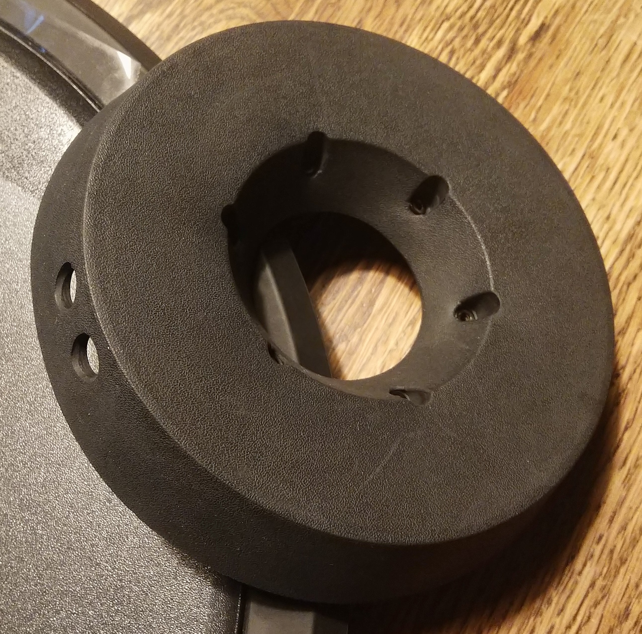
Remove the rubber housing
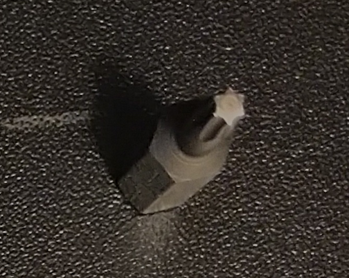
Remove the rubber housing from the underside of the cymbal.You need a T10 Torx driver bit to unscrew the 6 screws (it's a common driver bit for old desktop computer repairs).
The housing needs to be unscrewed and then pulled off the cymbal.
Be careful around the output jacks -- free that area last.
Each screw in the housing also has a washer -- sometimes they come out with the screw, sometimes they stay behind -- don't lose any.
Repair the first type of failure after the housing has been removed
I've had an 18" ride cymbal failure of the first type, and that is an easier repair.Just open up the housing and reseat the ribbon sensor into the PCB connection.
Gently pull the ribbon out of the connector and reinsert it back into the connector -- no jumper required.
Repair the second type of failure after the housing has been removed
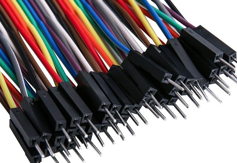
I've had 1 16" cymbal and 1 14" cymbal have edge trigger failures of the second type that I repaired as described here -- and the repairs have so far lasted years longer than the original construction.I had breadboard jumper cables sitting around, so I used those to fix the ribbon sensor connections.
The wire isn't used -- just the black handles and the conductive metal spikes.
The black ends make handling the conductive spikes easier and also prevent shorting out the ribbon.
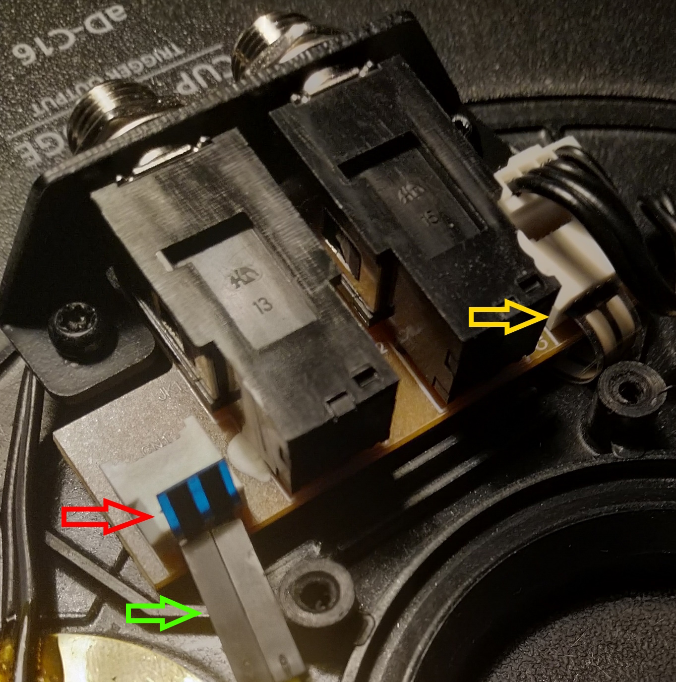
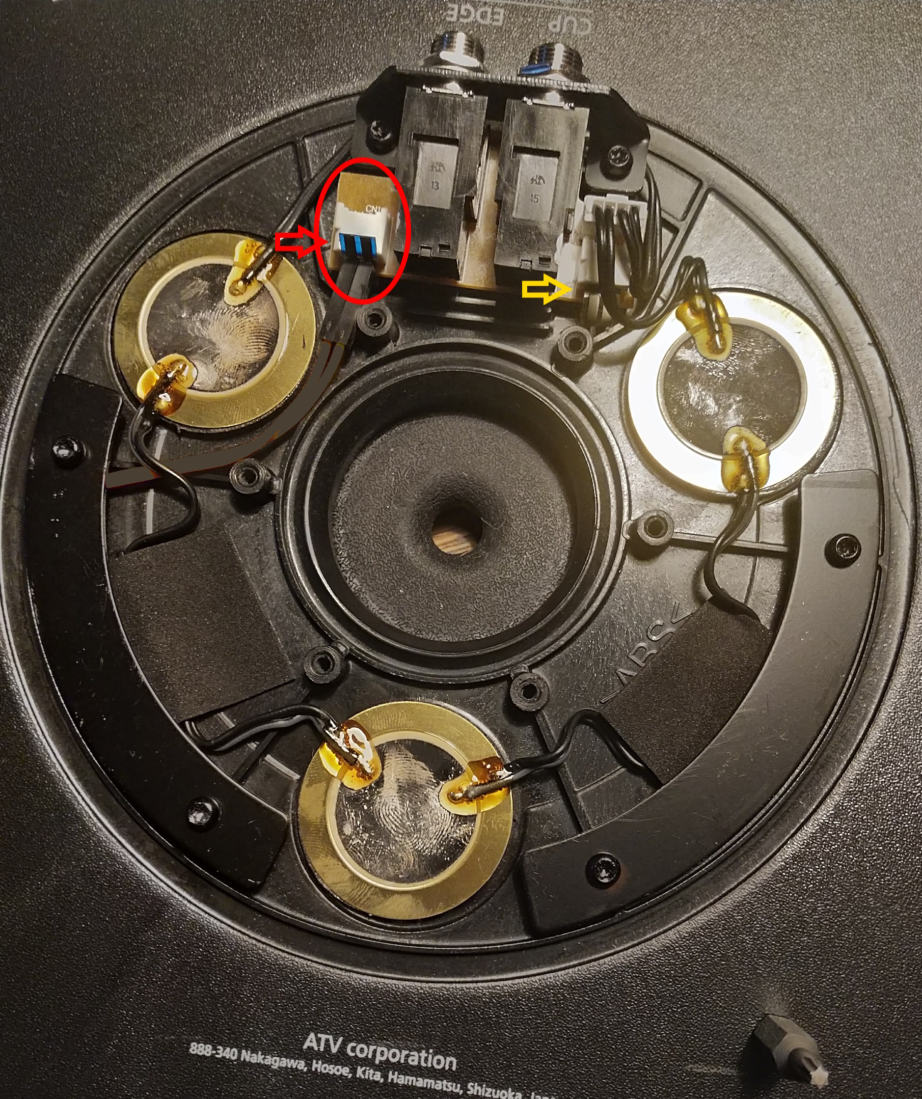
This is a picture of my first repair.
The red arrow points to the edge trigger ribbon sensor connection pulled out of the ribbon receiver.
The yellow arrow points to the bell trigger ribbon sensor connection.
Before repairing the edge trigger ribbon sensor connection, it will look similar to the one pointed to by the yellow arrow.
Gently pull the edge trigger ribbon sensor out of the PCB connection.
Use 2 stiff conductors of some sort (I used the breadboard jumpers) to pierce/stab each side of the ribbon below the bend in the ribbon and connect to the PCB ribbon receiver.
Bear in mind that there are two conductors in the ribbon sensor; don't short them out, pierce each one on its own, and connect to separate halves of the PCB receiver.
The two halves of the ribbon contain conductive material.
The repair replaces the ribbon inside of the PCB connector with something you provide that completes the circuit between the PCB connector and the conductive material in the ribbon.
If your ribbon is kinked or bent, make sure to pierce below the kink -- the kink near the end is the problem.
In this picture, again yellow arrow is the bell trigger ribbon connection, red arrow is the edge trigger ribbon sensor pulled out of the PCB and pierced by 2 breadboard jumpers called out with green arrow.